- Physics
- MagneticsNonlinear 2D FEA on datasheet B–H curves with a moving band, about 230 solves per design
- Cross-checkIndependent GetDP solver agrees to 0.001 % on torque
- DriveMinimum-current operating points with field weakening, for 6-step, SPWM and SVPWM
- LossesCopper, Bertotti iron, magnet and rotor eddy losses over an urban drive cycle
- ThermalCoupled thermal network that feeds magnet temperature back into the remanence
- NVH & demagRadial airgap force waves driving a rotor and rim model; worst-case demagnetising field
- Role of ML
- Gaussian-process surrogates, trained on 4,650 FEA designs, give instant feedback as you move the sliders and run the optimiser. Any design can then be confirmed with a full FEA solve in one click; the results below are all full FEA solves.
Background
The brief: a direct-drive hub motor that fits a 12" scooter rim and meets the EU moped class (45 km/h, 4 kW continuous, 72 V battery), with enough peak torque for a hill start. The open design questions were the ones every motor designer faces. Which slot/pole combination? How to shape teeth and magnets? Which magnet grade and steel? Radial magnets or a Halbach array, on steel or aluminium? And how do torque, efficiency, cogging, noise, heat and magnet cost trade against each other?
Approach
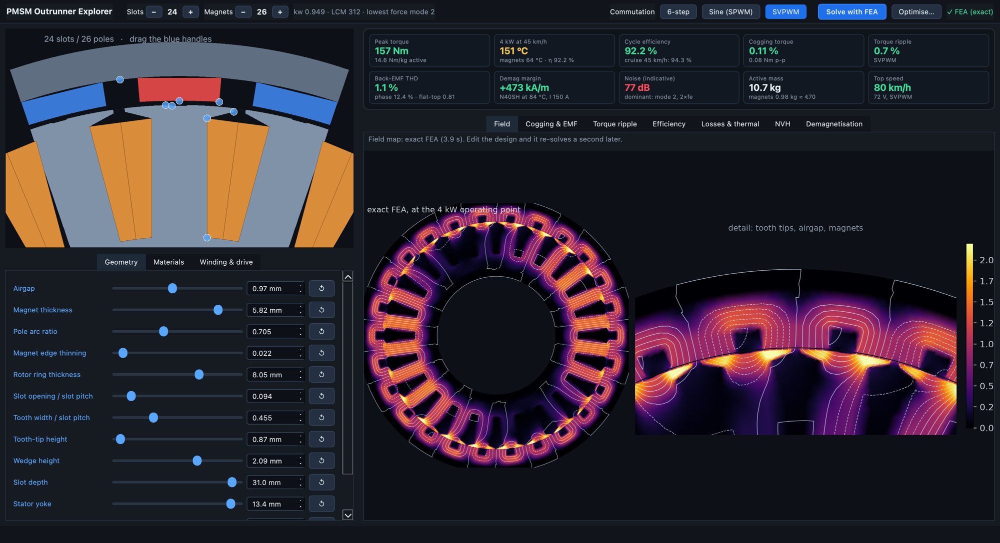
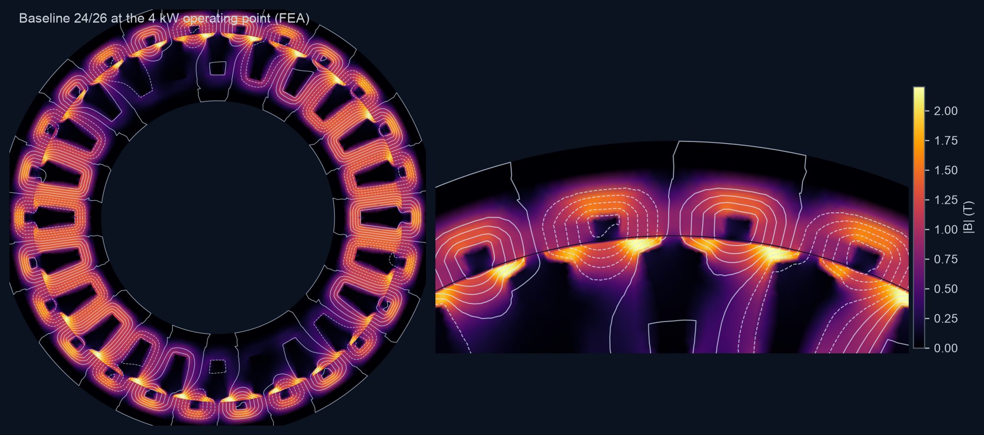
- Electromagnetics: a parametric outer-rotor geometry, meshed per design and solved with Newton–Raphson on datasheet B–H curves. Each design runs about 230 nonlinear solves, covering cogging, back-EMF, loaded torque ripple, d/q flux maps, losses, airgap forces and the worst demagnetising field.
- Drive and losses: minimum-current operating points with field weakening, for 6-step, sinusoidal PWM and SVPWM. Copper, iron (Bertotti, element by element), magnet and rotor eddy losses are evaluated over a realistic urban cycle with hills.
- Thermal and NVH: a coupled thermal network feeds magnet temperature back into Br. Radial force waves from the FEA drive a ring model of the rotor and rim.
- Interactive app: drag tooth and magnet vertices, step slots and poles ±, change materials and commutation, and every KPI updates instantly. A second after you stop editing, an exact FEA redraws the field map.
Where the ML surrogates come in
A full FEA evaluation takes 15–45 s, too slow for a slider or an optimiser. Machine-learning surrogates (Gaussian-process models trained on the FEA results) fix the speed. An optimiser running on a surrogate tends to settle where the surrogate is most optimistic, and at its first optimum this one overstated peak torque by 8 % (median, up to 16 %).
Two changes fixed that. Analytical magnetic-loading estimates (airgap, tooth and yoke flux densities, armature field) went in as inputs, so the model sees saturation coming. And optimiser candidates were verified with FEA and fed back in for two rounds. The error at the optimum fell to 1.8 % (median, 5.9 % at the 90th percentile).
Slot/pole study
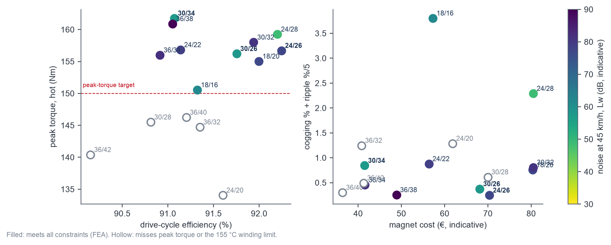
All 15 balanced slot/pole layouts (18 to 36 slots, 16 to 42 poles) were optimised with the same goals and constraints, and each winner was solved with the full FEA. 24/26 is the best all-rounder: 157 Nm peak, 92.2 % cycle efficiency, 0.7 % torque ripple. 30/34 gives the most torque (162 Nm) for the lowest magnet cost and is notably quieter. Several popular alternatives, including 36/40, could not meet the torque and 155 °C winding targets at once in this envelope.
Drive electronics
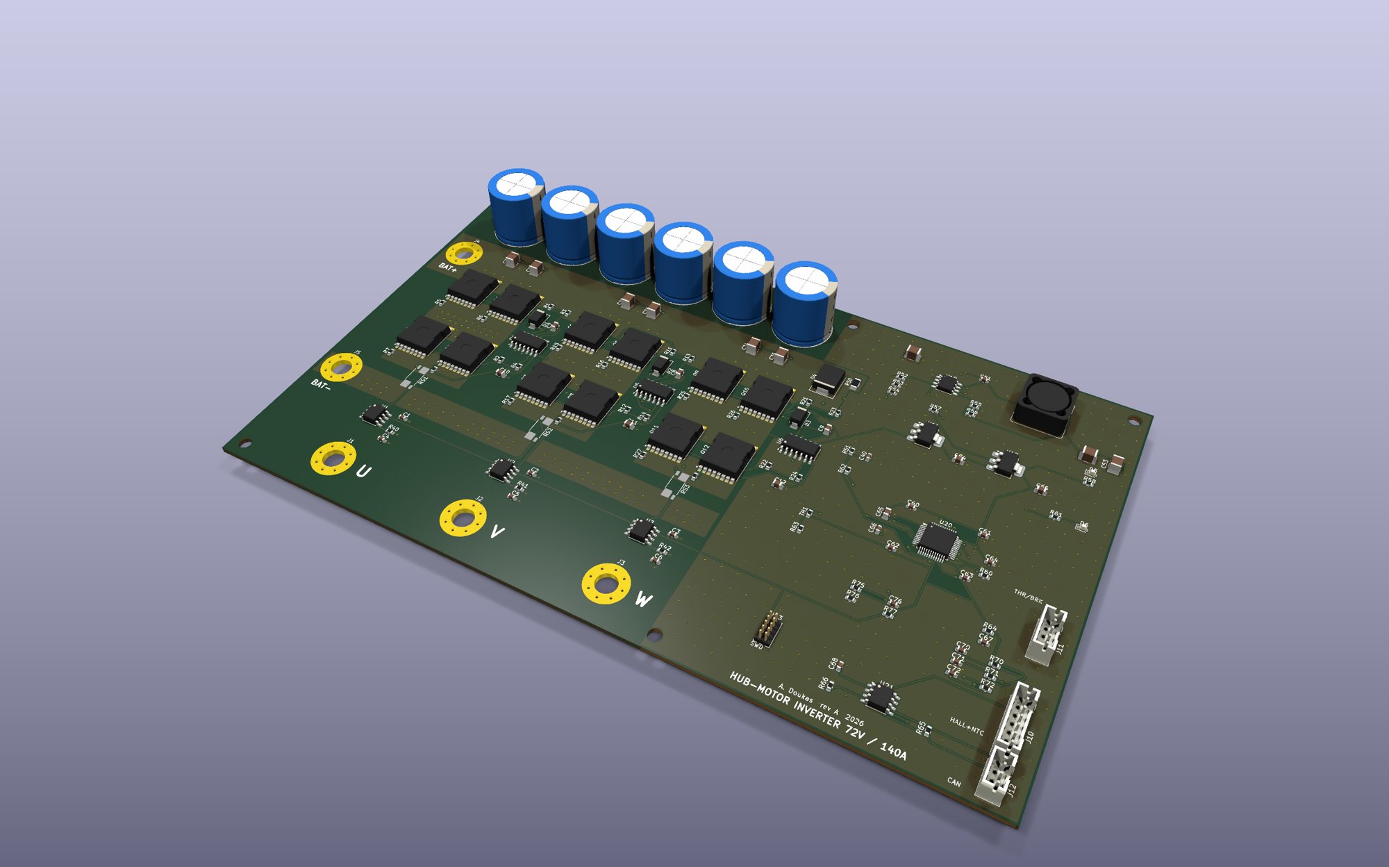
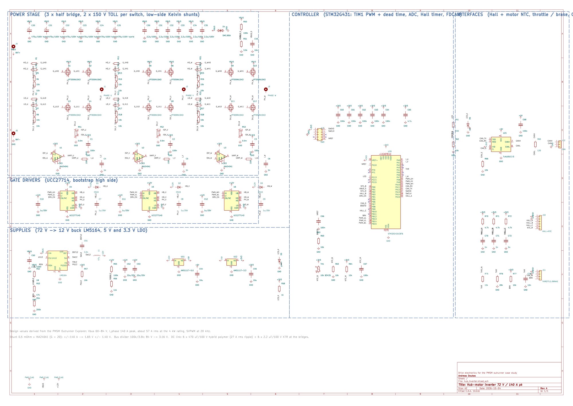
The inverter was sized from the motor results: 72 V bus, 140 A peak phase current, 27 A rms DC-link ripple. It was then drawn in KiCad: 150 V MOSFETs in pairs, bootstrap gate drivers, Kelvin shunts with current amplifiers, and an STM32G431 with Hall, throttle and CAN interfaces. Schematic and four-layer board come from one design file. The schematic passes ERC and the board passes DRC with zero violations. The bridge loses about 60 W at the 4 kW rating (98.6 %).
Results
- Peak torque up 22 % (129 → 157 Nm) in the same envelope. Cycle efficiency 91.4 → 92.2 %, cogging 0.3 → 0.1 %, ripple 1.1 → 0.7 %, demagnetisation margin up by a third.
- A defensible slot/pole choice, with the trade-offs quantified by FEA rather than rules of thumb.
- A standalone macOS app for further exploration, plus a technical report and the inverter design files.
- Stated limits: 2D FEA (no end effects), typical datasheet materials, no prototype measurements yet, and NVH levels are indicative.